In this article we will take at look LiDAR for everyday use by testing a DJI L1 lens at a controlled testing site.
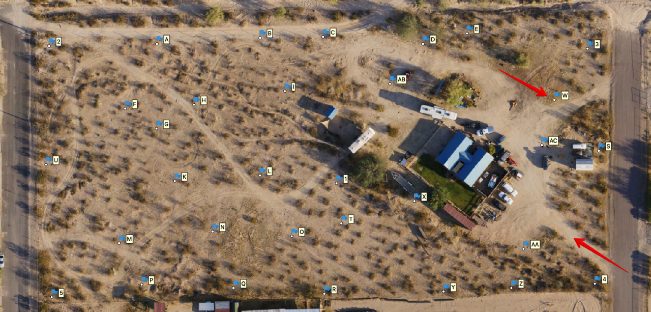
The objective for the test flight was to find the optimal workflow and flight height for repeatable survey grade accuracy results. The flight was performed at 200 feet AGL (Above Ground Level). The test site was configured with 35 permanent panels where each had one hour of static performed on each point and (OPUS) corrected for X, Y coordinates. Levels then ran for vertical. The horizontal datum is set to NAD 83/Arizona Central 202. Vertical is set to NAVD 88. Thank you to Jim Crume PLS, MS, CfedS, RP, Survey Manager, Cooper Aerial Surveys Co for assisting with this testing.
JUMP TO SECTION
TEST SITE
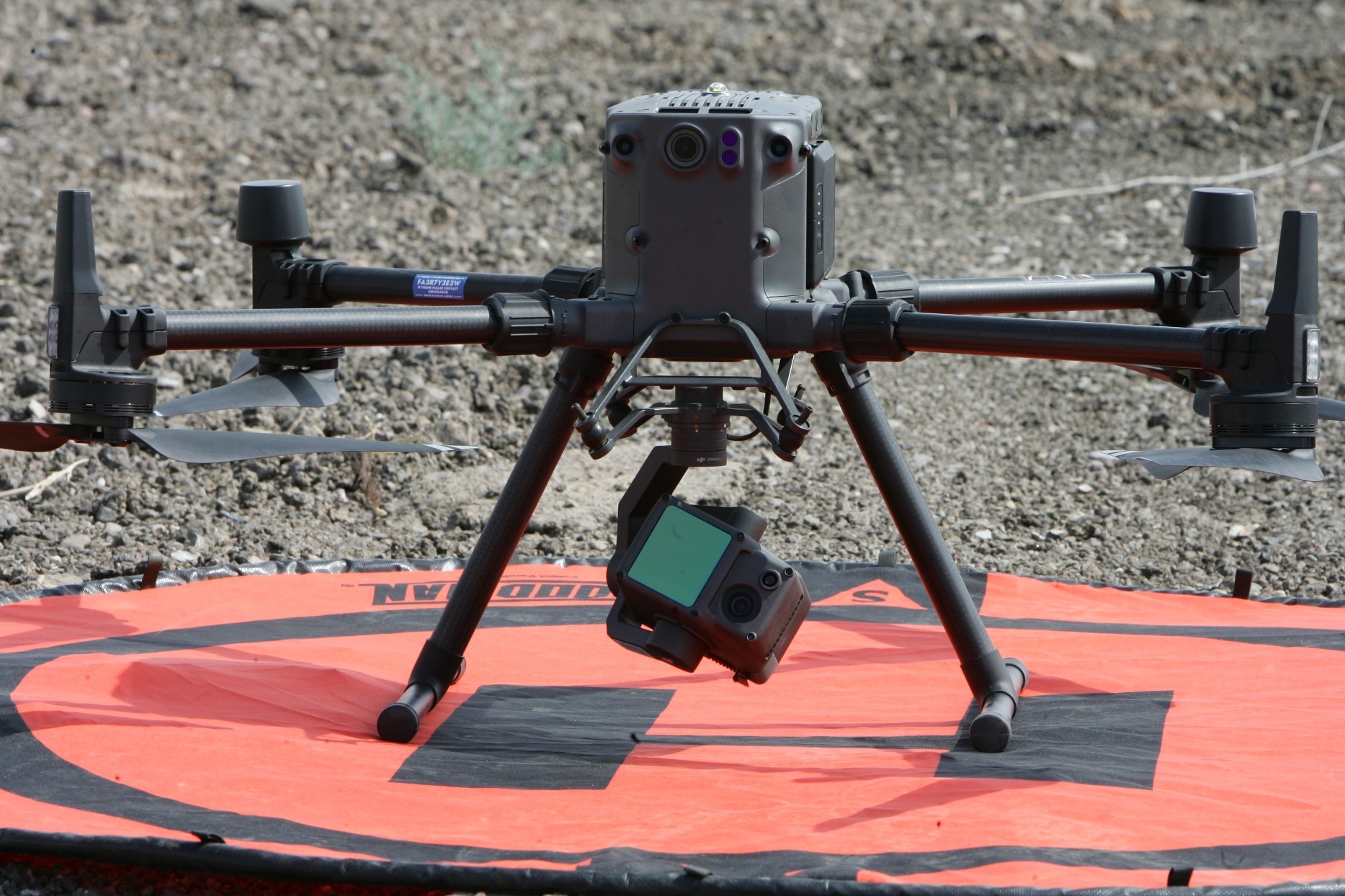
DRONE SET UP
M300 with the L1 lens.
TEST FLIGHT SETTINGS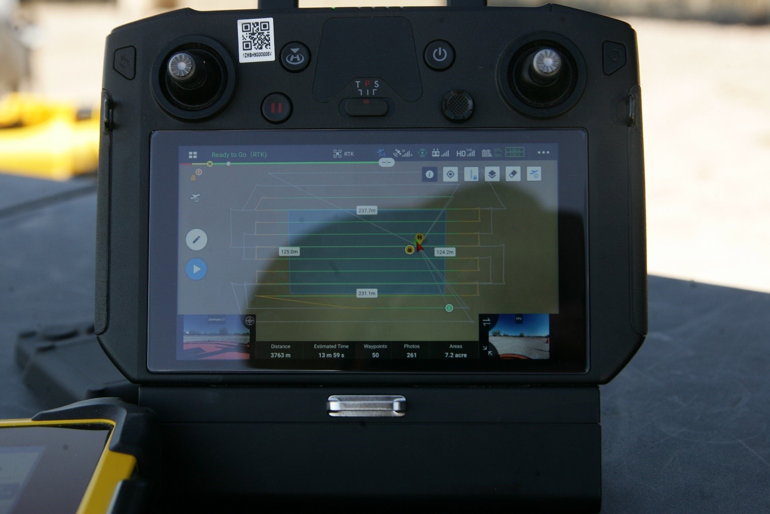

- Maximum Flight Distance
- Needed for L1 in flight calibration
- 1500m/4921 ft
- Altitude Mode
- Relative to take off point
- Flight Route Altitude
- 61m/200 ft
- Flight Speed
- 10m/s
- Overlap
- 30%
- Return
- Triple
- Scan Mode
- Single
- Color Scan
- On
RTK was used during the test flight. RTK corrections were sent to the drone.
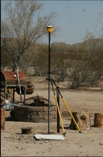
 RTK SETUP
The SPS 986 rover setup was over a known site control point and the rover was setup as the WIFI hotspot. A Trimble T10 tablet field controller was connected to the rover and the web interface was used to set the latitude, longitude, and height of the known control point. The DJI flight controller was then connected to the rover WIFI IP address.
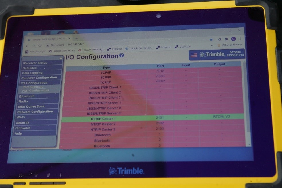
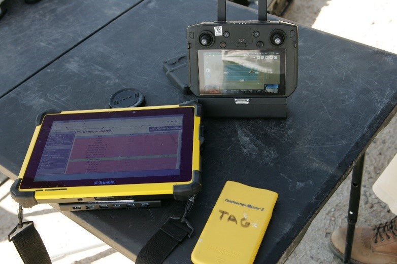
Image of DJI flight controller connect to the rover IP address.
 With this setup, the RTK correction was sent to the M300 during the flight. A hot battery swap was also performed during the flight to see if this would cause issues. When the RH (Return Home) button was pressed, the M300 returned home to its last location and continued with the rest of the flight mission with no loss of RTK corrections.
POST FLIGHT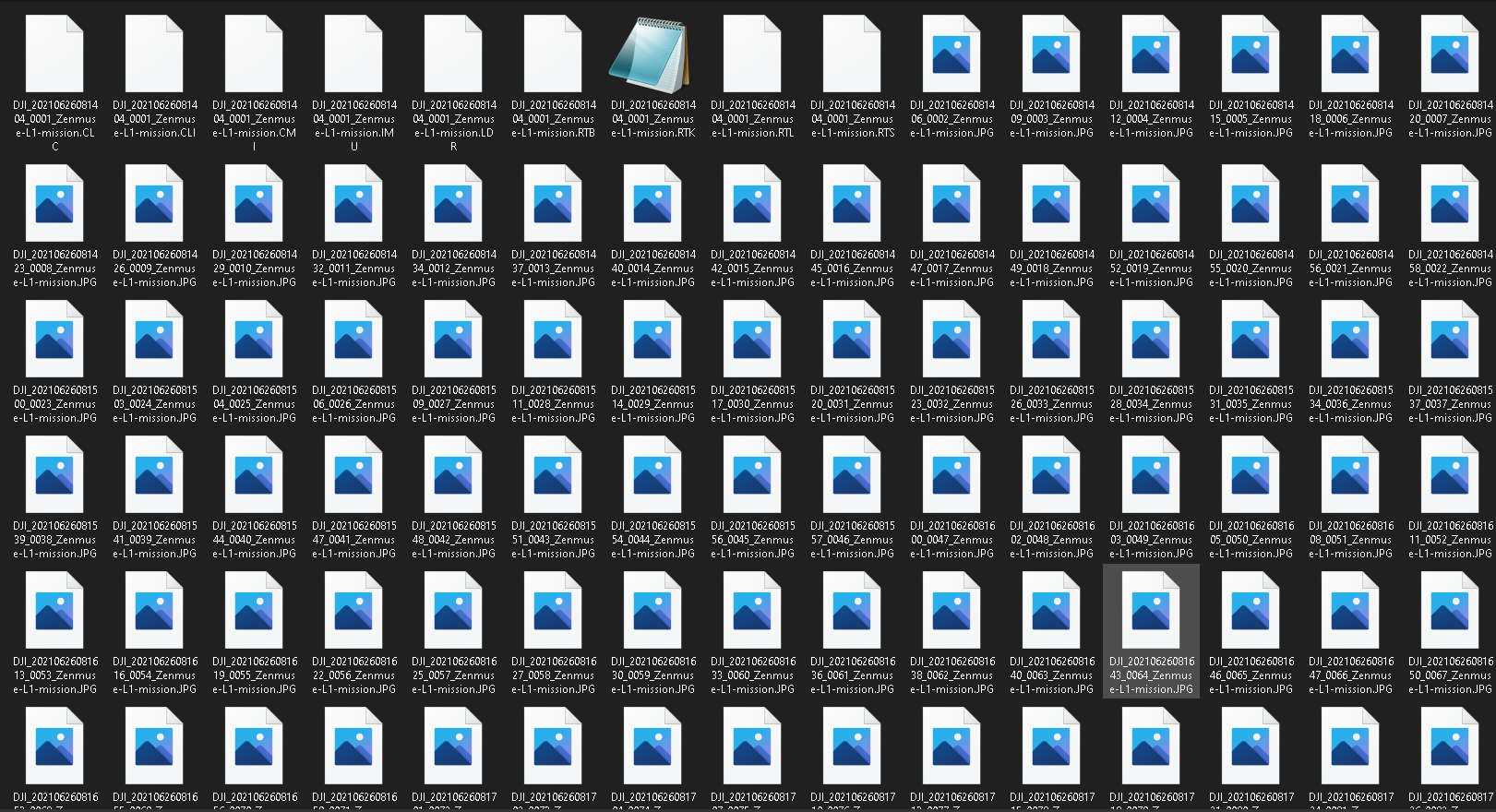

The flight data was downloaded from the SD card in the L1. The L1 writes the LiDAR raw files as well as the jpg images.
PROCESSING
Processing data from the DJI L1 needs to be done in DJI Terra. This can be processed in the free version. If processed with the free version, you will not be able to optimize the point cloud. The optimization can only be done with the electricity version or the full version. We plan on conducting further testing to analyze the differences.
Importing L1 data into Terra is very simple. Just follow these steps:
- Create a LiDAR processing mission.
- Direct it to the folder of the data.
- Set the output coordinate system.
- Hit process.
Once the process is done, the point cloud will show on the screen.
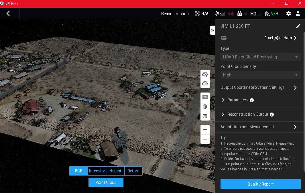
You will then be able to interact with the point cloud by rotating, zooming in and out, and getting X, Y, Z values of the points. If everything looks good, you’re ready to export out the point cloud to be used in Trimble Business Center (TBC).
Trimble Business Center WORKFLOW
The point cloud data is brought into a TBC project that was setup to the site coordinates.
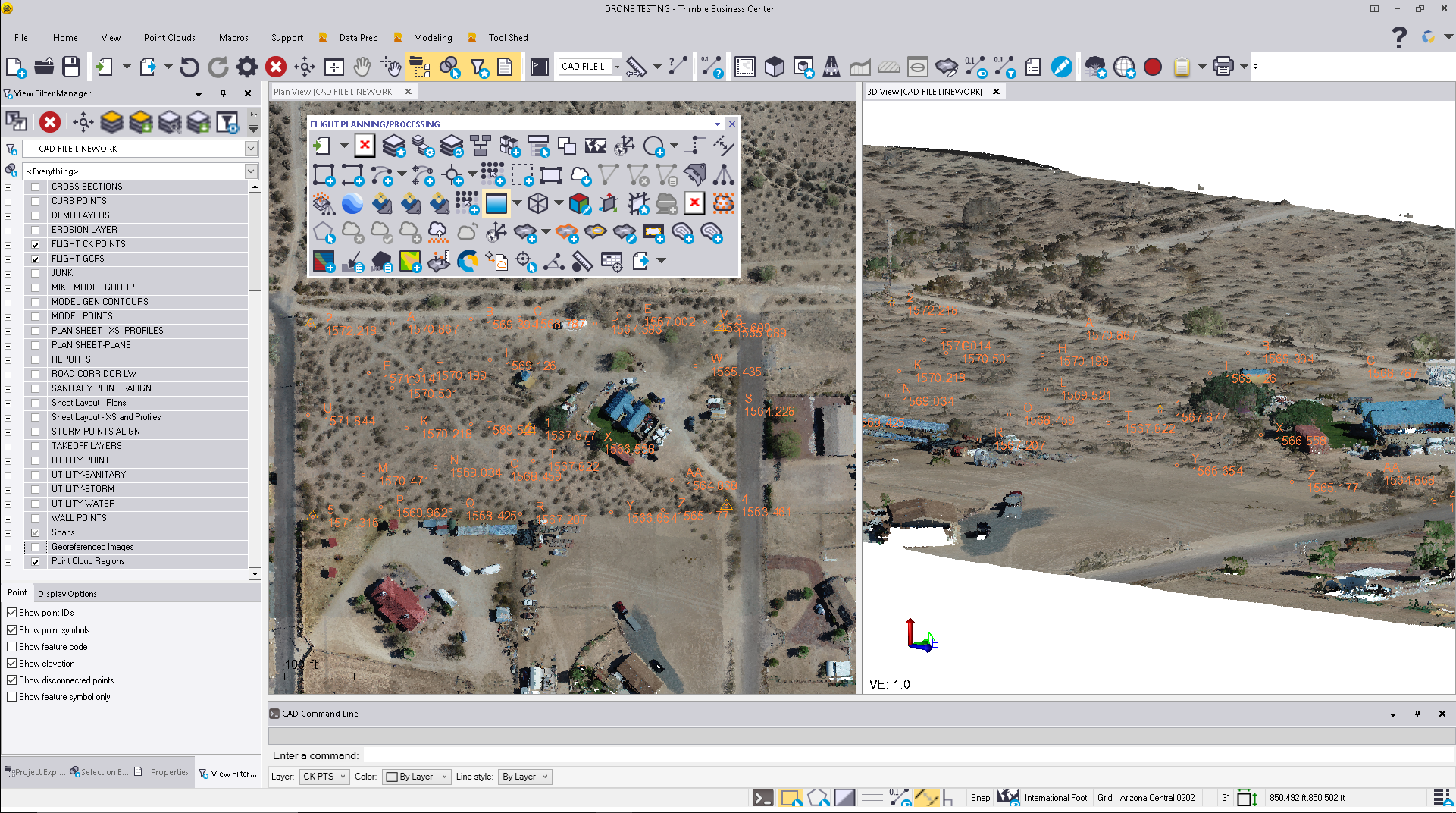
UAS Master was also used to create a True Ortho of the site from the photos that were taken during flight. The Ortho was then imported into TBC. A georeference of the point cloud to 5 GCP’s (Ground Control Points) was performed in TBC during this testing. We were looking for major X, Y shifts. We saw between .1’ to .35’. Was this caused by doing in flight colorizing of the point cloud? We will investigate this during future test flights. In the meantime, this shift was addressed during the georeferencing process.
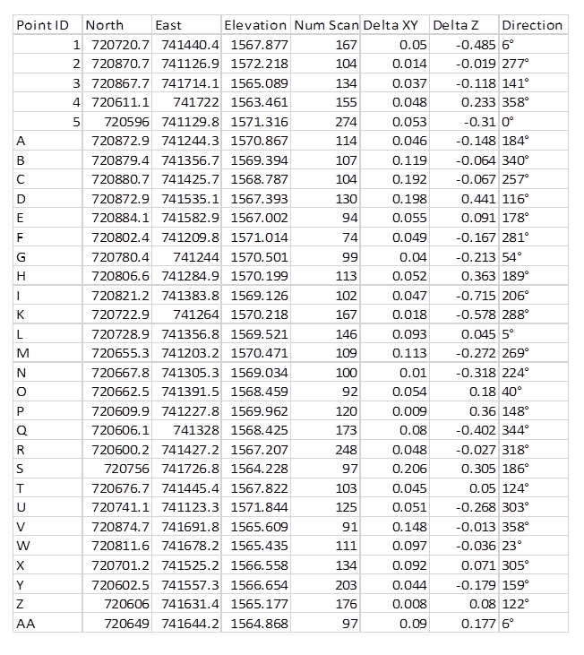
Point cloud was extracted to ground, trees, and building with the extraction tool in TBC. A point-to-point cloud analysis report was run as the final step on the test.
The points fall with the predicted range from the flight height. Could we see issues in vertical being caused by in flight colorization of the point cloud? This will also be tested.
Point-to Point Cloud Report from TBC
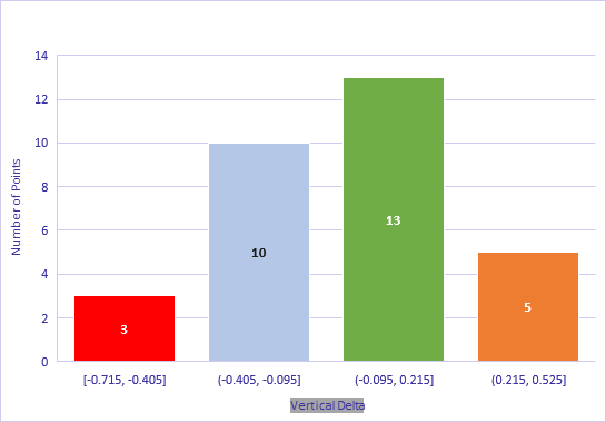
200 ft AGL FLIGHT CONCLUSION
The M300 with the L1 payload flown at 200’ AGL, in a very tightly controlled site, produced results that were in expected range with the current workflow in place. More tests will be needed to analyze the results of flight at heights of 100 -150 AGL. This is where we are predicting the sweet spot of repeatable accuracy will be. The plan is to re-fly and analyze all three flight heights with the change in the scan mode from single to repeat, along with single and double returns in the workflow.
If you are thinking of adding this to your current fleet or just getting started. You will not be disappointed in this purchase. To find out more about DJI’s UAV solutions contact us today!