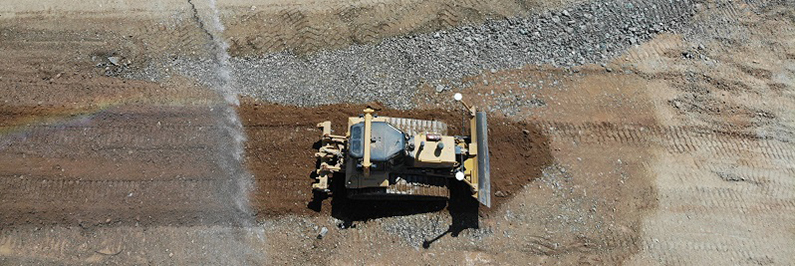
With the growing popularity of GNSS systems for machine control and site positioning in construction, there is a need for a basic understanding of coordinates. During daily operation, operators and grade checkers will not need to work with coordinate systems. However, having someone on site that has a basic understanding of coordinate systems can eliminate downtime and site errors.
JUMP TO SECTION
Coordinate Definition
First let’s determine what a coordinate is. The Webster dictionary defines a coordinate as
“Any of a set of numbers used in specifying the location of a point on a line, on a surface, or in space.”
In construction, coordinates are used in lines, surfaces, and features. They are normally expressed as the following:
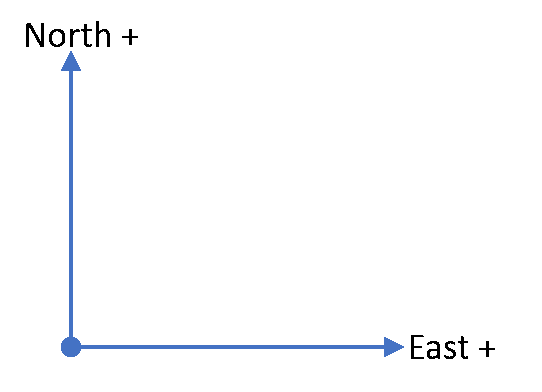
- Northing
- Easting
- Elevation
On the other hand, GNSS works in a global system and can be expressed as:
- Latitude
- Longitude
- Height
Types of Coordinate Systems
There are two basic types of coordinate systems in construction: Cartesian and Spherical.
Cartesian
 A coordinate based on a plane or grid
- Reported as distance from a origin point, in X,Y
- Can be expressed globally or locally
- Typically, either State Plane or a local coordinate
Spherical

 A global coordinate based on a mathematical ellipsoidal datum
- In GNSS the WGS84 datum is used
- Reported as latitude and longitude
- Not very useful on a construction site
Making GNSS Coordinates Useful
One of the first tasks in preparing a site for GNSS operation is to convert the GNSS Spherical values to a useable Cartesian value. To do this, we need a set of transformation parameters containing the relationship between the two values. These parameters are calculated in two ways.
Site Calibration
A Site Calibration is supplied by the site engineers and calculated by surveyors. This is the preferred method. If a site calibration is not available, one can easily be created in the Trimble SPS Controller.
How it Works
During the measurement of the control points the controller calculates a horizontal and vertical adjustment parameter. The horizontal and vertical adjustments are computed separately. Control points can be horizontal and vertical, horizontal only or vertical only. These parameters are:
- Horizontal
- Rotation
- Translation
- Scale
- Vertical
- Block shift
- Tilted plane
- Geoid Separation
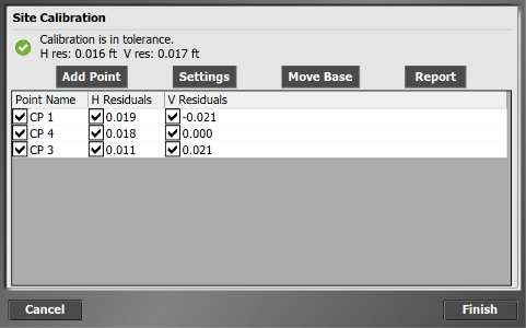 As control point observations are added, the controller refines all the observations for a best fit solution. After three observations have been completed the controller will start to display horizontal residuals
Steps in performing a Site Calibration
- Load a Comma Separate Values (CSV) file containing the local control point name Northing, Easting, Elevation.
- Take a measurement at each control point.
- Minimum of 3 points, 5 or more points are preferred.
- When finished measuring the control points:
- Review the residuals and if within tolerance, accept the calibration.
- Export the calibration for use on the machines.
Published Coordinate System
Published coordinate systems are based on a global or local definition. One part of the definition is the datum used. A datum can be simply defined as a starting point or origin of a coordinate system. This starting point is usually in WGS84 latitude and longitude. To use a published coordinate system, we must be on the same datum. This can be done in two ways, setup the base station over a known point and enter in the latitude, longitude and height, or measure a known point with the rover as a datum shift. In most cases this would be a ‘US State Plane’ system. The parameters to use a State Plane system are already in the data controller.
Using a US State Plane Coordinate System
 There are few items to be aware of when using a published State Plane system.
- A datum shift must be measured prior to using the coordinates.
- It’s preferred that the base be setup at a control point with known Geodetic coordinates in the State Plane datum.
- The coordinates are based on a grid that is at mean sea level (MSL).
- When connected to a GNSS receiver, Trimble data collectors display distances in ground units.
- If the controller is connected to a Total Station (optical Instrument), the grid to ground scale factor must be used.
Elevations
I did not cover elevations in this segment as it would make the document too big to follow. So, I will cover the vertical component of a coordinate in a later article.
Conclusion
No matter what type of coordinate system your site uses, the Trimble SPS controller makes easy work of the transformation. You just need to measure a few control points and let the controller do the rest. Once the transformation is complete for a site, you will not need to do it again. Just transfer the site calibration to all machines and controllers. Don’t forget if you run in to problems, SITECH Southwest has a knowledgeable staff to help with any issues you may have.